DBSTAR SYSTEM MANUAL
1. Synchronization system topology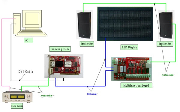

2. Computer selection and installation steps
Host: 1 PCS empty PCI slot, 1/pcs available USB interface.Hard disk: Greater than 100M free space after installing operating system.
RAM: Above 64M.
CPU: Above Pentium 300MHZ.
Video card: Above standard VG256 display mode.
Software environment: windows 95/ 98 / NT / 2000 / XP / VISTA
Micrsoft media player must be installation.
Office2000 — If you need to display word, then must be install.
Real player — If you need to display document, then must be install.
● To sum up, the common computers are usually ok for use.
2.1 Installation of video card and controlling card
a. Shut off the power, pull up the plug, open the chassis.
b. Insert the video card into the VGA rabbet.
c. Insert the controlling card into the PCI rabbet, as shown in the picture below:
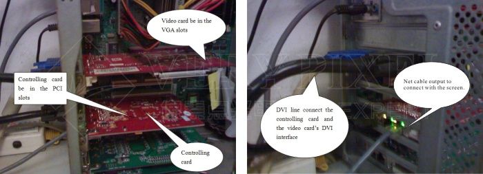
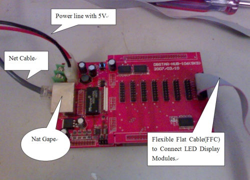
Connecting receiving card inside the LED display:
3. Special notes
3.1 Pull up the net cable and electrify the LED screen. If the screen is blank after all the connections, we can judge the connection is normal .Contrarily, if light spots or light lines appear, we can judge the system connection is abnormal.3.2 Please choose the net cable from regular manufactures, or it is to affect transmission distance.
4. PC parameter settings
The first step: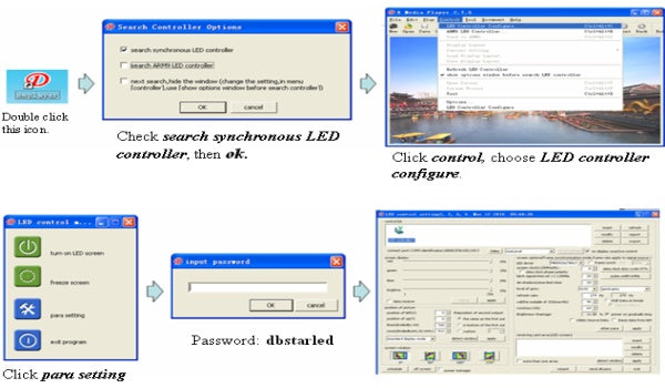
The second step:
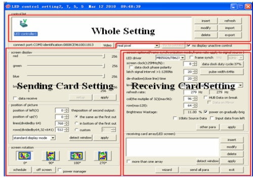
Some points to be noted during setting process
Sending card setting:
● When you set the items under “position of picture”, you should choose according to display resolution.
● “Schedule” button means running corresponding operation within a specified time.
Receiving card setting:
● The refresh frequency's setting, as the situation below:
Photograph by the camera is non-flickering: above 600Hz.
Dual color display: 60-75Hz.
To full color screens, general-use effect for indoor is 180-600Hz and for outdoor is 300-1200Hz.
● Gray level setting:
Dual color 256, full color indoor 4096, outdoor 16384 will be ok.
● The selection of LED driver chip:
The chips supported by DBT-Q2007 receiving card: MBI5026, MBI5024, Tb62726, Tb595, MBI5027 etc.
The chips supported by DBT-Q2009 receiving card: MBI5026、BI5024、TB62726、TB595、MBI5030、MBI5036、MBI5039、MBI5042MBI6030、MBI6020、DM413、LPD6803
5. Simple software operating procedure
Double-click the icon XMplayer and enter the software operating interface after installing the software.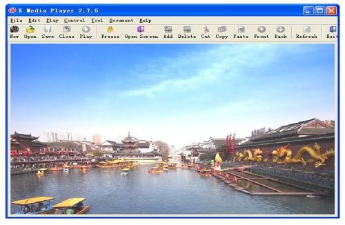
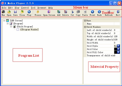
The simple understanding of interface
The process of programme production
The first step: setting the size of play window.
The play window size must be set right, or when you broadcast the program, it will just show the program partially.
Two ways of setting:
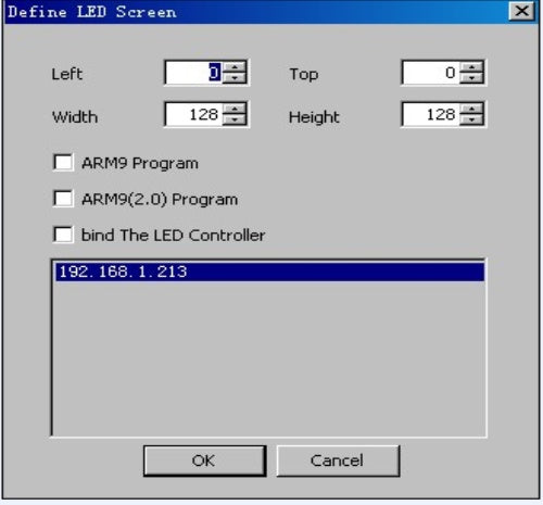
New establish (New establish on the tool bar or menu -> file-> new establish), the following figure will appear:

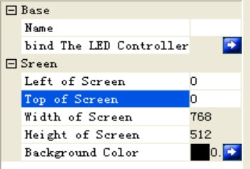
Fill in the value of the left side, top, width and height according to the needs and finally "OK"
The second kind: the client can select "bind the LED controller" for setting, in this way, the size and place of the screen will be achieved automatically (The premise is that the user has established it), finally”OK”
The specific procedure is as follows:
The second step: establishing new program list
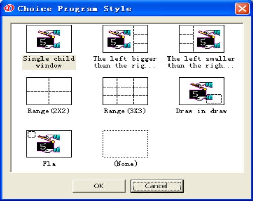
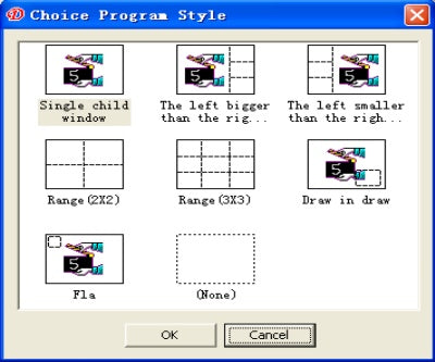
After setting the size of the screen, the following diagram appears. You can make choice according to needs, and then click “Ok”.
Click “New” bottton , like following figure
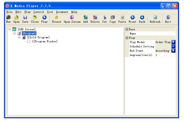
Left click [LED screen] and the property table will be displayed:
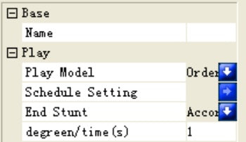
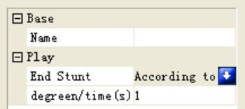
Left click [Program] to display the property table:
Left click [Subprogram] to display the property table:
Left click X [Program window] to display the property table.
X: represents the serial number of the window of the subprogram under the subprogram, for example: 1 [Program window]
The third step: Option of setting the program window

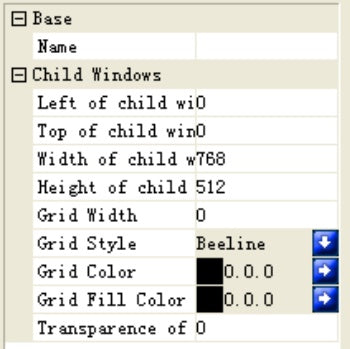
The figure below illustrates the new-established program window with name, place, size of the program window, frame type, frame color, background color of the frame and the transparency of the sub-window.
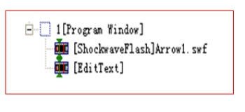
The forth step: adding program materials
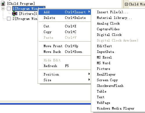
The fifth step: Setting the option of the program materials
The property is modified after adding the materials according to the needs, for example, adding Flash file, and editable text:
The sixth step: finishing program manufacturing
Click the save button or select the menu file-> save.
The seventh step: the playing program shall play the current program files
click the tool bar (or) play the button to start playing, pause stop or select from the control menu. When playing different program files, click open button and playing will be conducted after opening the program file.
6. Basic fault and fault elimination
1. Interruption of the connectionThe specific representation is:
a. Unsuccessful parameter sending and [connection interruption] will be suggested;
b. Failure to find the control card;
c. The interface of the software fails to adjust, which means under gray status. The software [LED control equipment list] has no main control icon.
Methods used to probably solve problems:
a. Pull in and out of USB wire again;
b. Change USB wire;
c. The equipment manger checks the equipment connection;
d. The computer is confirmed without virus;
e. If it is under internal type, it is probably due to the loose slot or dirty part of PCI. Please insert again or adopt the rubber to wipe the PCI interface.
2. No-signal output
The specific representation is:
The indicator light for main control output network port is not light.
Methods used to probably solve problems:
a. <XMPLAYER> has not been installed, please check installation;
b. Failure to open the FPD of the display card. Right click my computer on the desktop-> property-> setting-> senior-> display-> FPD;
c. Incorrect resolution mode:
The specific representation is: the screen flashes is or under uncontrollable status.
Methods used to probably solve problems:
Adjust the current resolution of the computer to be in accordance with that of the control card.
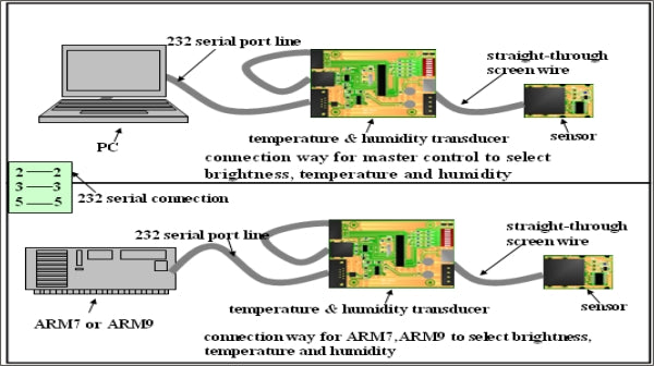
7.Special Function Description
Brightness sensor, temperature and humidity sensor.Function: Adjust Led display brightness automatically, sense and react to the temperature and humidity of LED display.
The connection schematic diagram is as follows: